Sometimes the conveniences of using an Arduino board start to conflict with the performance that you expect, at least from a strict engineering point of view. When you develop with the Arduino Integrated Development Environment (IDE), there are some things you need to know to understand the processing delays, functions, and how to overcome them by using traditional Microcontroller (MCU) coding techniques.
Arduino libraries have a great deal of overhead that is meant to protect boards from damage by people that are new to electronics.
For instance, reading from or writing to a pin takes much longer than most new developers realize. In most situations, this doesn’t cause a problem, but for a project with a time-critical process, like accurate stepper control or data acquisition, for example, it can be a problem. One workaround, or an alternative way to manipulate the MCU registers, is by using C or assembly language.
Why Arduino?
Arduino boards and the Arduino IDE are incredibly versatile and therefore are employed in a variety of applications. In education, they provide a low-cost physical “breadboard” for students to test sensor inputs, act upon those inputs, and then create an output to generate an action in the physical world. The traditional path of engineering design might require students to understand the entire 662-page datasheet of the ATmega328P microprocessor (PDF) just for the microprocessor itself. However, the Arduino platform allows students to jump ahead so they can quickly enjoy the physical results of their coding exercises.
In the world of art and hobbies, Arduinos allow users to control electronic devices without spending years studying electronics, learning how to spin a Printed Circuit Board (PCB), or surface-mount solder tiny SMD components. The Arduino objective is to produce a final result that’s fairly unrelated to being an expert in the details of PCB design. The Arduino platform (hardware and software) allows users to circumvent many tedious steps and get to the result they need right away, without costing an ARM or a leg.
For engineers, Arduinos provide a documented, off-the-shelf prototyping platform that is widely accessible primarily because of its low cost. In some cases, engineers use the Arduino platform as a prototype or proof-of-concept for a custom design. For smaller production runs or one-off designs, it may be more economical to use the Arduino itself in the final design.
At some point, the convenience of using an Arduino begin to conflict with the expected performance; at least from a strict engineering point of view. For folks to use Arduino microprocessors variants effectively, they need a deeper understanding of the Arduino IDE, functions, and development environment.
Arduino and microcontroller pin mapping
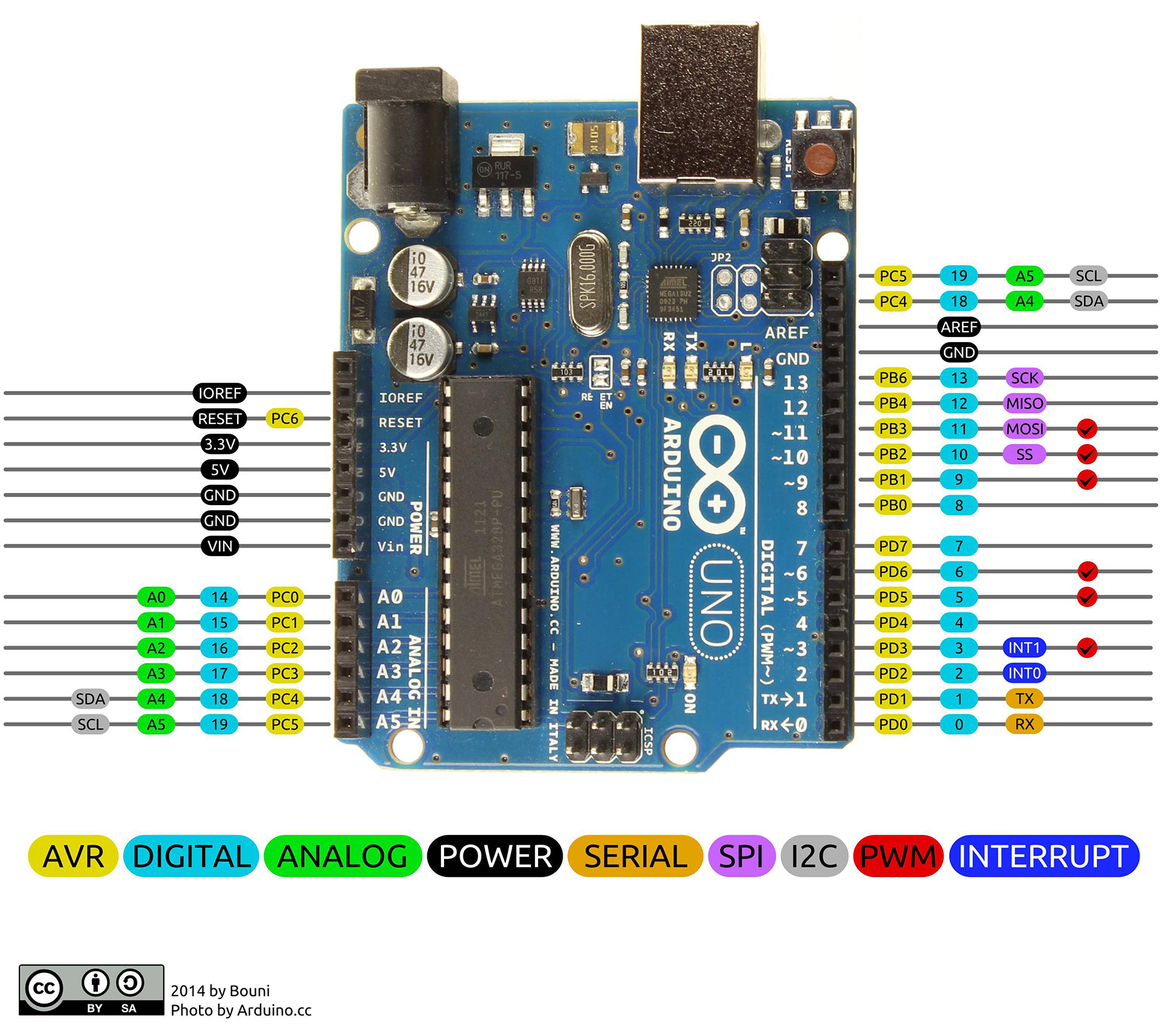
To begin the workaround mentioned above, users first need to understand how the MCU pins are mapped to the Arduino pins. Figure 1 shows the relationship of the Arduino pins to the ATMega328p MCU ports, registers, and pin positions. If you are only concerned about using Arduino IDE functions, all you need to worry about are the Arduino pin numbers. But if you want to program using the corresponding microcontroller’s pin numbers, you need to make the translation from one to the other.
For example, writing to pin 8 using an Arduino function would be “digitalWrite(8,HIGH)”. However, to write to pin 8 by coding directly to the microcontroller, you would set bit 0 of the PORT B register (PB0). Clearly, Arduino pin 8 is actually, from the perspective of the MCU, bit number zero on Port B. (Figure 1).
Digital I/O using Arduino-mounted MCUs (without using Arduino IDE functions)
Microprocessors used in the most common Arduino designs are of the AVR type. (AVR used to be an Atmel product, but now is owned by Microchip Technology, Inc.). Arduinos that operate at a higher speed or with more complex peripherals will use an ARM-type microprocessor.
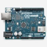
Arduino UNO Rev 3 was populated with the ATmega328P. General Purpose Input Output (GPIO) pins are controlled by three microprocessor registers: DDxn, PORTxn, and PINxn.
- The DDxn in the DDRx register selects the direction of the pin. (Direction meaning “is it an input or an output?”).
- PORTxn selects the internal pullup resistor when it is used as an input.
So, setting up a microcontroller pin is just a matter of inserting a few steps in the initialization of the microcontroller code:
- Set the pin as an input or output.
- If set to an input, enable or disable an internal pull up resistor.
From there, reading the value of an Input/Output (IO) pin is just a matter of reading the value of a bit in the pin-status register of the MCU. Writing to a pin is just a matter of setting or clearing a value in the status register. Setting a high value in software results in a corresponding high value at the external pin of the MCU. (The voltage of the HIGH GPIO output depends on the logic level used for the Arduino, typically either 5Vdc or 3.3Vdc.) Software instructions like this will result in a physical voltage change at the microprocessor pin in just a few instruction cycles. While you can code these register instructions directly in C, modern compilers like the Arduino IDE will give you the same fast instruction cycle result.
In a typical microprocessor design, the time it takes for the engineer to look the register values up once and then code to the register value thereafter is well worth the performance improvements. In fact, traditional, pre-Arduino microprocessor development would have the engineer do this without a thought to the additional complexity encumbering the Arduino environment, which favors code portability and safety over concise, quickly executable code.
Digital I/O using Arduino functions
For an Arduino IDE design, there are two steps placed in the “Setup” coding block:
- Set the pin mode during setup.
- Enable or disable an internal pullup resistor if the pin is being used as an input.
From there, read or write the external pin value using the digitalRead or digitalWrite command. This can be done within the Setup block to get or set the initial values, but more typically these functions are called in the Loop block either directly or through another function in the loop or an interrupt service routine.
The Arduino Setup and Loop blocks are like the microprocessor-based design method. In principal, this is good training for the new developer to understand that you need to follow the identical process. However, without understanding the underlying code of the Arduino IDE functions, the new developer can also be led astray.
digitalRead
Compare digitalRead to a traditional embedded microcontroller solution where an I/O pin can read by reading the bit value of the corresponding register. However, the digitalRead function of the Arduino IDE looks like the below (Figure 2):
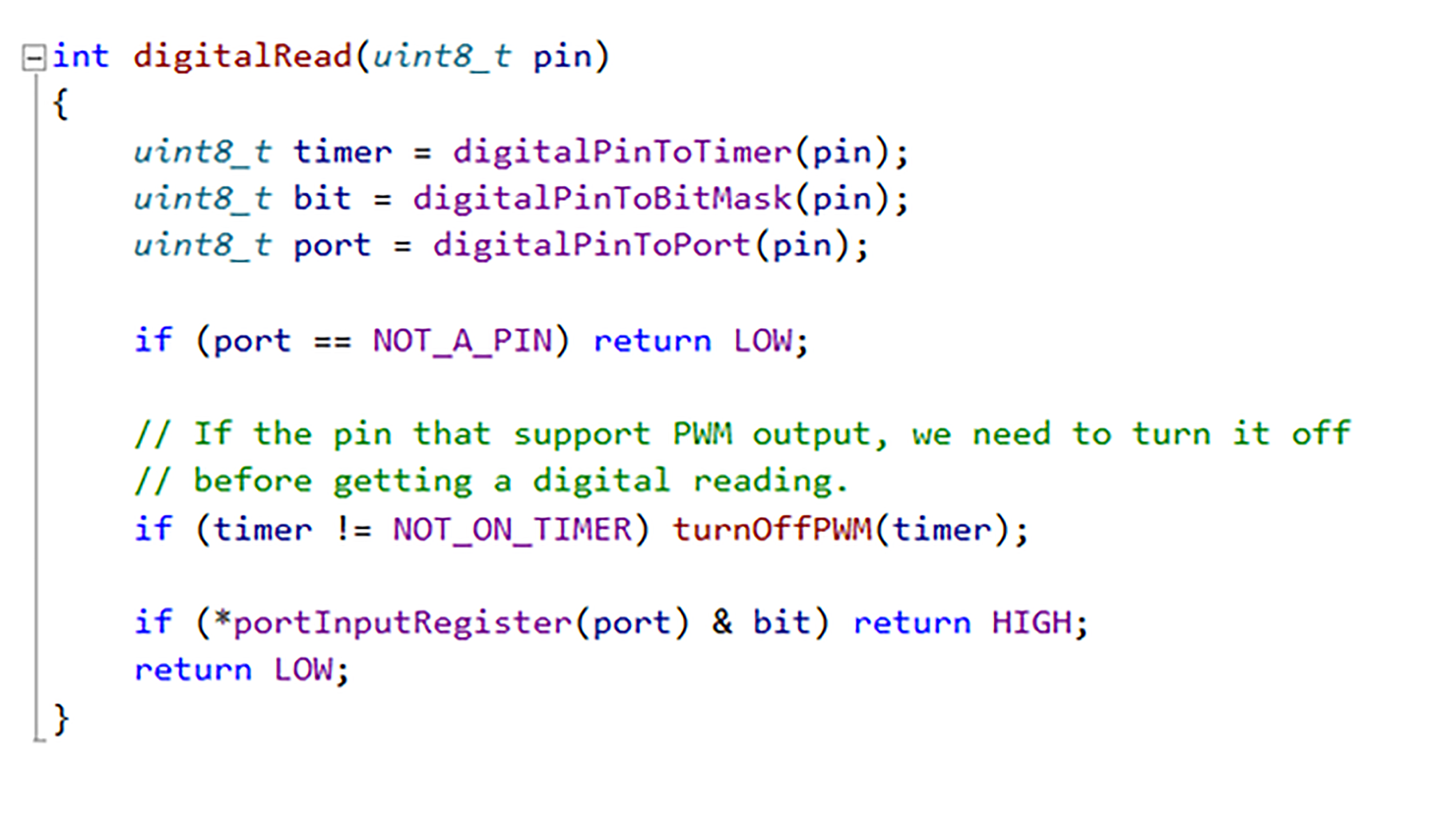
The script in Figure 2 creates additional overhead for each digitalRead call:
- uint8_t timer = digitalPinToTimer(pin);
Performs a look up of the internal timer that’s used with a particular pin when you’re directly using the MCU for the chosen Arduino variant of the project. The timer is in use if Pulse Width Modulation (PWM) is being used for the noted pin (see above bullet). But in this case, we’re performing a digital read of the pin. PWM is not involved, but the standard Arduino IDE call wants to look up this value anyway.
- uint8_t bit = digitalPinToBitMask(pin);
The above statement performs a lookup of the port register position that corresponds to the desired I/O pin. While you do need to know the port register position, the value doesn’t change between subsequent reads. Therefore, the value could be defined in the setup and called only during the program’s execution. Looking it up for each digital read is inefficient.
- uint8_t port = digitalPinToPort(pin);
The above performs a lookup of the MCU port that the pin is tied to. Again, while you need to know this, it won’t change between subsequent digital read calls. Therefore, the value could be defined in setup and called during program execution.
- if (port == NOT_A_PIN) return LOW;
Checks to see if the result of the Digital-Pin-to-Port value is an actual pin that’s available for use in the selected Arduino MCU variant. This doesn’t change between subsequent digital read calls. In a typical MCU design, using an undefined pin is a mistake that will create some higher-level debugging, however such redundancy in coding isn’t typical. However, the use of redundancy in the Arduino IDE would prevent the program from locking up entirely if this undefined pin mistake were made, but would result in a huge hit to processing time.
- if (timer != NOT_ON_TIMER) turnOffPWM(timer);
Despite trying to take a digital reading, this line is disabling the PWM timer used for the output function. While it’s technically possible that a pin mode might be changed from an input to an output in the middle of an embedded program, it is not typical. In an embedded system, the purpose of an I/O pin is defined and remains that way. If the design runs out of pins….then other options like using the available communications busses would need to be explored.
- if (*portInputRegister(port) & bit) return HIGH;
return LOW;
The above lines of code read the related GPIO pin and return a corresponding HIGH or LOW value to the program.
All of the extra calls ensconced within the Arduino functions are overly safe, but at the cost of 50 to 100 extra instruction cycles, versus just reading the corresponding bit of the GPIO pin whose status you want to know. Arduino functions do have the advantage of flexibility and portability, but at the cost of efficient, quickly executing code.
digitalWrite
Digital write has all of the same overly safe but largely inefficient calls that are part of digital read, but digital writes provide even more inefficiency.
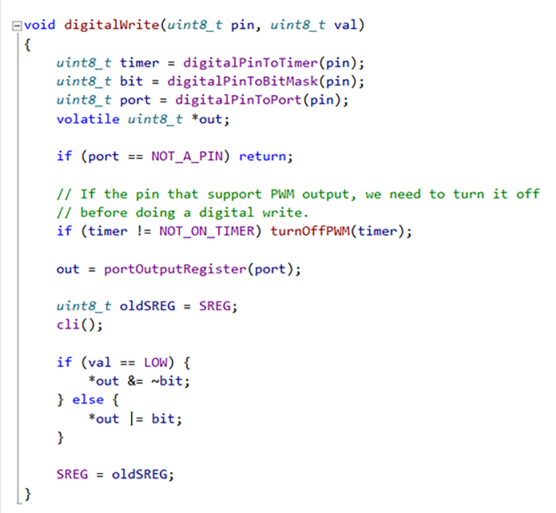
Examining each statement in Figure 3:
- volatile uint8_t *out;
out = portOutputRegister(port);
Creates a temporary variable ‘out’ every time digitalWrite is called. This could be a global variable that is created once, during the MCU’s initialization.
- uint8_t oldSREG = SREG;
cli();
SREG = oldSREG;
This smidgen of code saves the microcontroller’s Status Register, which contains the interrupt enable status flag. Global interrupts are then disabled using ‘cli()’. Disabling all interrupts while writing data out to a pin might prevent a race condition if that pin were also used as an external interrupt input, but this is a rare case that is solved by careful coding in a more typical microprocessor coding solution. Only a limited number of pins are available for external interrupts on an Arduino anyway (e.g., pins 2 and 3 for an Arduino UNO).
- if (val == LOW) {*out &= ~bit;} else {*out |= bit};
The above IF-ELSE statement adds at least a dozen instruction cycles. Typically, other logic in the code is determining if a high or low should be output on the pin. For code that responds more quickly, simply performing the bit manipulation directly at that point would be all that’s needed ( &= |= ).
Conclusion
Depending of the intended use of the Arduino, the Arduino IDE functions may be sufficient for what the user needs to avoid all the high-level coding…. just to get the desired end result. The portability of code across dozens of different Arduino boards is just one strength of Arduino IDE functions. On the other hand, Arduinos should not be dismissed as “hobby level” devices, as the same MCUs are used in commercial and industrial designs. Programming the MCU populating an Arduino can be just as efficient as programming a custom designed prototype, especially if the custom designed prototype hasn’t arrived yet from the hardware team.
Thanks for the informative post. It helped me a lot. May the Force be with you.
Thanks for sharing the informative post. It helped me a lot. <3