LiDAR systems and ToF techniques are critical to providing self-driving cars with a detailed picture of the surrounding and is used in many research applications as well. This is the final part of a four-part series on LiDAR systems and ToF techniques.
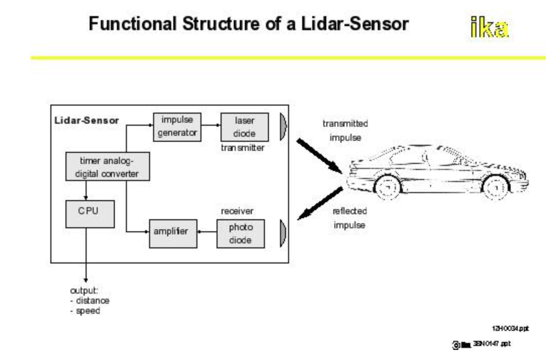
The high-level block diagram of a LiDAR system inherently glosses over the many functional blocks and subfunctions of the hardware and does not show any of the software (Figure 1).
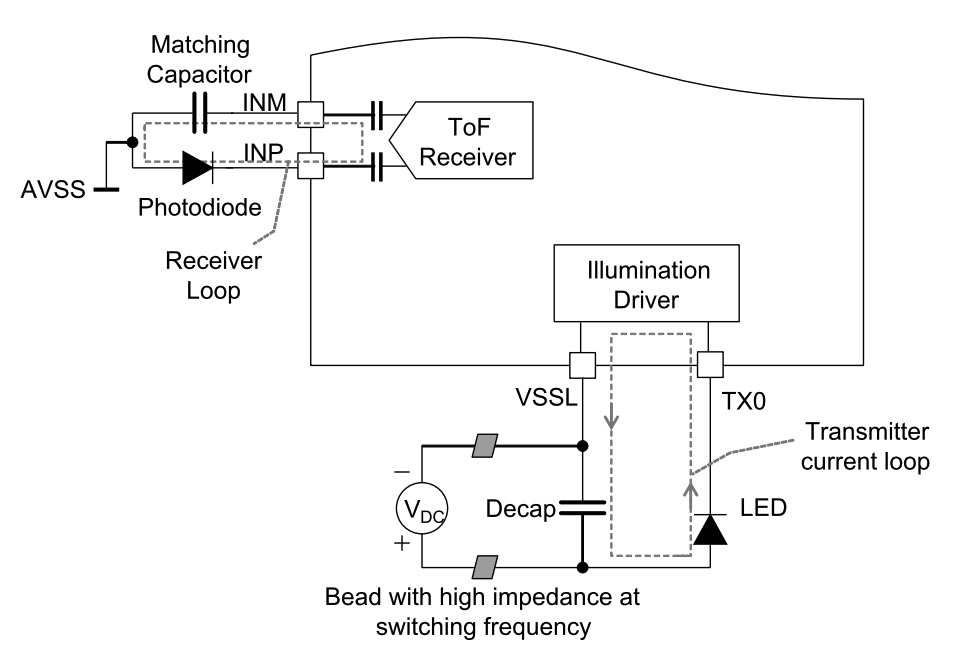
A simplified illustration of the interface requirements for the optical source and sensor in a LiDAR/ToF implementation can be supported by a single IC such as the Texas Instruments OPT3101 (Figures 2a and 2b). But a complete LiDAR requires more circuitry and channels.

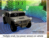
Besides the emitter and sensor pair, there are lots of R&D related to replacing the mechanical scanner with a solid-state version. SWEEPER, one of the many DARPA projects, a system has been developed the synthesized beam can be sweep over a 50⁰ angle at 100,000 times a second (10,000× the mechanical mirror speed (Figure 3). However, the sweep angle may be too narrow for many aspects of the autonomous car; again, it’s only at the starting point of a new technology. Alternatively, if the electronic version can be made small and inexpensive enough, it may make sense to use several of them in an overlapping configuration and stitch the individual images together if needed.
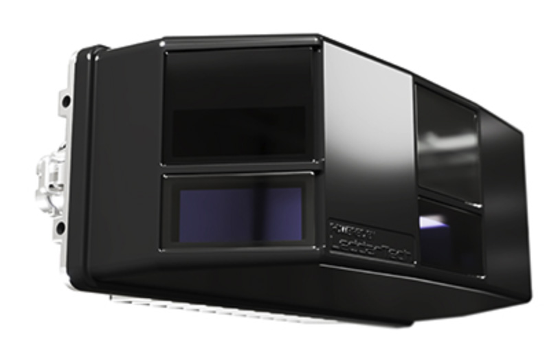
Some commercial, non-military non-mechanical systems are already on the market, such as the Innoviz Pro unit from Innoviz Technologies Ltd (Figure 4), with a 73° × 20° (horizontal/vertical) field of view and 0.2° x 0.45° angular resolution (H/V).
Next time you see or read about the autonomous cars coming “soon,”, just remember that there may be an old-fashioned, mechanically rotating mirror for the LiDAR systems at the top backed by incredible processing power and advanced algorithms — at least for now. Then remember that ten years ago, the idea of a placing 77-GHz radar system in a mass-market product such as the car was almost unthinkable. Yet, now, it is available as a standard feature on many vehicles. It’s not impossible that all-electronic LiDAR may be the next disruptive technology for cars and other 3D imaging applications.
What about calibration?
There are very few optical and electro-optical systems which do not need per-unit calibration, and LiDARs are not exempt from this requirement. This is due to their complexity, the wavelength of the optical signal, the critical alignment of the many components and paths, and unavoidable fabrication and manufacturing tolerances and tolerance buildups. Many detailed analyses of the issues have been presented, and the need for calibration is a cost and maintenance issue in automotive and other LiDAR systems.
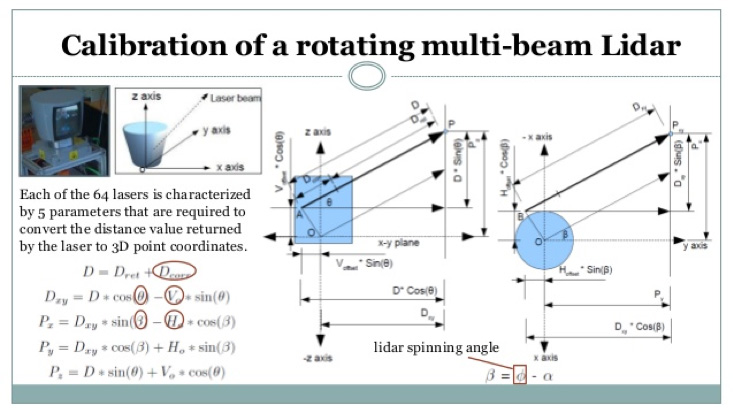
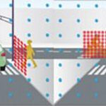
The analysis involves geometry, physics, optics, electronics, and more, and the fixturing for tests, alignment, and calibration gets very complicated (Figure 5). One of the many challenges in employing LiDAR systems in mass markets such as cars is designing a system which does not need routine re-calibration, and which functions to specifications despite time on the road, and which can even self-calibrate in the field to some extent — even if its specifications degrade somewhat compared to doing a calibration done in a dedicated fixture.
LiDAR is a complicated and necessary part of making autonomous or near-autonomous vehicles into a reality. It is a vital part of the instrumental used for aerial mapping and many other scientific endeavors. It requires a sophisticated blend of optical, analog, and processor technologies, integrated with complex algorithms. There’s no question that making it into a viable mass-market function is an ongoing challenge.
EE World References
- Autonomous vehicle sees with LiDAR eyes
- A better way to measure lidar
- How can picture-like images be obtained from LiDAR?
- Doppler Lidar for Autonomous Cars Excels in Real-World Tests
- At Autonomous Vehicle Sensors Conference: Upstart Lidar Companies Face Off
- GaN FET driver excels at solid-state light detection and LiDAR apps
- What advanced sensing techniques are used to find lost treasures? Part 5: LiDAR
- The Future Of LIDAR For Automotive Applications
- LiDAR: How The Next Generation Of Radar Mapping Works
- Vacuum tubes we still (have to) use: The photomultiplier tube, Part 1
- Vacuum tubes we still (have to) use: The photomultiplier tube, Part 2
External References
- IEEE Spectrum, “Lidar-on-a-Chip: Scan Quickly, Scan Cheap”
- Tech Briefs, “Real-Time LiDAR Signal Processing FPGA Modules”
- NASA, “A Survey of LIDAR Technology and its Use in Spacecraft Relative Navigation”
- Laser Focus World, “Lidar advances drive success of autonomous vehicles“
- DARPA, “SWEEPER Demonstrates Wide-Angle Optical Phased Array Technology”
- NOAA, “What is LIDAR?”
- Terabee, “Time of Flight principle”
- Terabee, “A Brief Introduction to Time-of-Flight Sensing: Part 1 – The Basics”
- AMS AG, “Time-of-Flight Sensing”
- All About Circuits, “How Do Time of Flight Sensors (ToF) Work? A Look at ToF 3D Cameras”
- Texas Instruments, “ToF-based long-range proximity and distance sensor analog front end (AFE)”
- Texas Instruments, “Time of Flight (ToF) sensors”
- Texas Instruments, SBAU305B, “Introduction to Time-of-Flight Long Range Proximity and Distance Sensor System Design”
- Texas Instruments, OPT3101 Data Sheet
- National Center for Biotechnology Information, S. National Library of Medicine, ”A Fast Calibration Method for Photonic Mixer Device Solid-State Array Lidars”
- Yu Huang, “LiDAR for Autonomous Vehicles”
- Geospatial World, “What is LiDAR technology and how does it work?”
- American Geosciences Institute, “What is Lidar and what is it used for?”
- National Ecological Observatory Network (NEON), “The Basics of LiDAR – Light Detection and Ranging – Remote Sensing”
- Hamamatsu Photonics, “Photodetectors for LIDAR”
Leave a Reply