Bits are the 1s and 0s that form the basis of digital information. A group of 8 bits is a byte and forms the basis of digital computing. Bits and bytes are used for storing and processing information as well as other functions in a digital IC. This FAQ begins with a brief review of 8-, 16-, and 32-bit MCUs, then looks at special function registers (including control bits and flag bits), arithmetic logic unit (ALU) bits, and configuration bits.
Classifying MCUs as 8-, 16-, or 32-bit designs is only one way to distinguish their performance capabilities. The number of bits identifies the size of the registers. For example, there are 8-bits per register in an 8-bit MCU. It also identifies the available memory addresses, 28 (or 256) in an 8-bit MCU, and the largest number that can be processed (also 28 or integers 0 to 255) in an 8-bit MCU. 16-bit and 32-bit MCU have correspondingly more bits per register, more available memory addresses, and can handle larger numbers compared with their 8-bit counterparts. For example, a 32-bit MCU can handle quadruple the amount of data compared with an 8-bit device. And an unsigned integer variable in an 8-bit MCU consumes a single byte while the same variable requires 4 bytes of data in a 32-bit device.
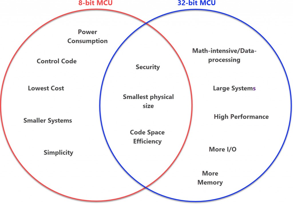
In addition to bits and bytes, MCUs can be classified according to their operating frequency, onboard memory size, numbers and types of I/O ports, and other characteristics, resulting in numerous performance tradeoffs (Figure 1). In general, 8-bit devices are more basic implementations designed for simpler control functions than 16-bit and 32-bit MCUs. A 32-bit MCU can have an operating frequency of hundreds of MHz, while an 8-bit design often operates at only 8-MHz. The 32-bit device can process much more data quicker than the 8-bit MCU. So, while 8-bit devices are well suited for use in consumer white goods, wireless internet of things (IoT) sensor nodes, and other simple applications, if the application calls for buffering large amounts of data, a 32-bit MCU is often the better choice.

Special function registers
Special function registers (SFRs), sometimes called special-purpose registers, or just special registers, control or monitor specific aspects of MCU operation. Each hardware device in an MCU will be assigned at least one SFR; more complex devices can be assigned multiple SFRs. Different MCU implementations and architectures have different sets of SFRs that perform functions such as:
- Controls for I/Os and peripherals
- Timers
- Stack pointers and stack limits
- Program counters
- Condition codes representing the result of previous comparisons
- Subroutine return addresses
- Processor status, such as running in protected mode or servicing an interrupt
SFRs are often not directly writable and require special instructions to modify them. SFRs are composed of control bits and flag bits. Control bits are used to turn a function ON or OFF when a 1 or a 0 is written to that location in the SFR. Flag bits indicate the existence of specific conditions.
Flags register
The FLAGS register contains the current state of the MCU, and its size and structure vary for different MCU architectures. Information about restrictions on MCU operation and the results of arithmetic operations are among the contents of a FLAGS register. Examples of restrictions include preventing the execution of certain ‘privileged’ instructions or stopping some interrupts from triggering.
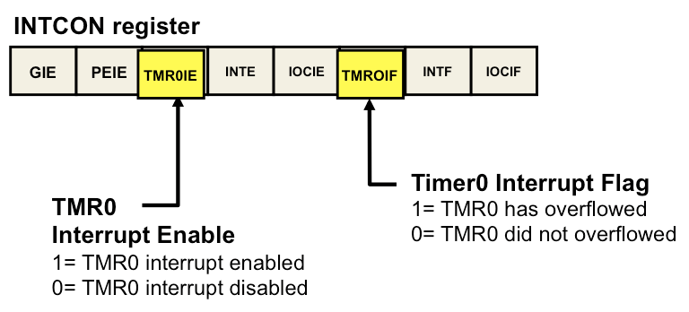
For example, in some MCUs, every time the TMR0 register overflows, the TMR0IE interrupt flag bit of the INTCON register is set, whether or not the Timer0 interrupt is enabled. That allows the Timer0 (TMR0IF) interrupt flag bit to be polled asynchronously by the software.
When the Timer0 interrupt enable bit of the INTCON register is set to 1, the automatic interrupt is enabled. When the interrupt is enabled, and the TMR0 register overflows, the MCU directs execution to the interrupt vector, which is needed to hold the address of the software interrupt routine. In addition, the Interrupt Service Routine (ISR) can preload the TMR0 Interrupt Enable register and clear the Timer0 Interrupt Flag when an overflow occurs (Figure 2).

ALU flag bits
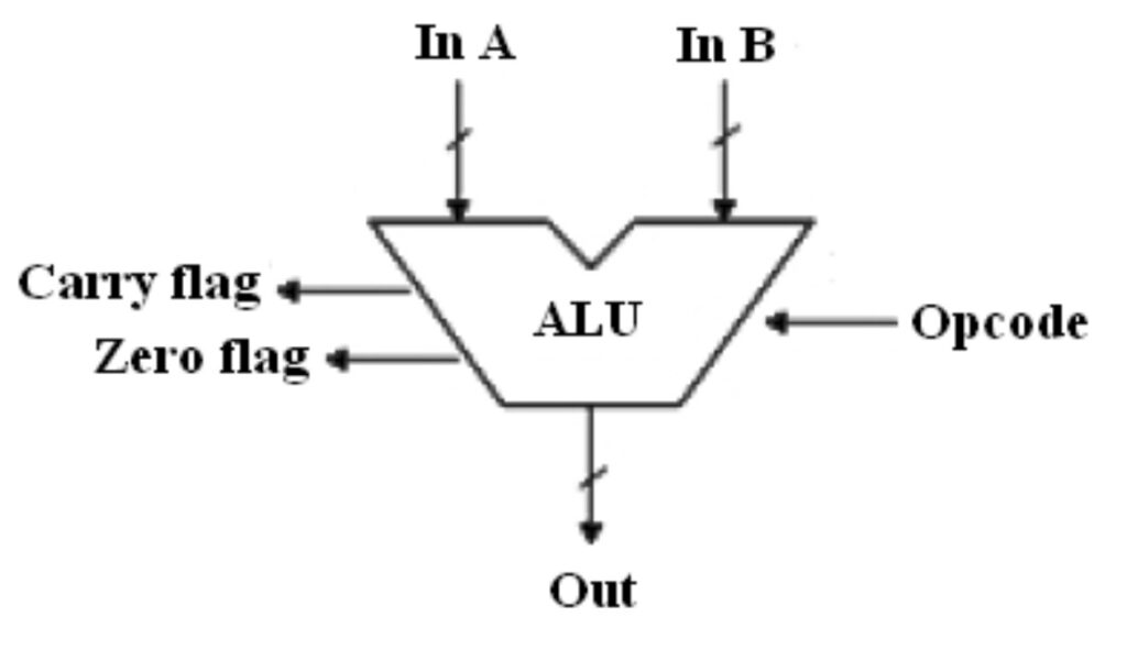
The ALU handles the math and logic functions of an MCU. The ALU flag bits store the results of math operations and can be read at any time. The two most common ALU Flag bits are the zero bit flag and the carry/borrow bit flag (Figure 3):
- The Zero Bit gets set to a 1 whenever a math operation has a result of 0 and is cleared to a 0 whenever a math operation has a non-zero result. One use of this bit is to compare two numbers by subtracting them. If the numbers are equal, the result of the subtraction will be 0, and the Zero Bit will be a 1. If the numbers are not equal, the subtraction will return a non-zero result, and the Zero Bit will be a 0.
- The Carry/Borrow Bit is used as a carry flag for addition operations and a borrow flag for subtraction operations. When the result of an addition operation returns a value larger than the register can hold, a ‘carry’ happens, and the carry flag is set to 1; if no ‘carry’ happens, the carry flag is set to 0. When a subtraction operation returns a negative result, the borrow flag is set to 0, and if a subtraction operation returns a positive result, the borrow flag is set to 1.

Configuration bits
Configuration bits are not executable code and can only be modified at program time. They are read during startup to enable or disable specific features in the MCU. Examples of common configuration bits include:
- Selecting oscillator options
- Setting the power up timer and brown-out reset.
- Watchdog timer settings
- Selection of ‘high power’ or ‘low power’ operating mode
- Enabling hardware debugging to take place
- Enabling the use of an extended instruction set mode
- Controlling if the MCU resets if the stack underflows or overflows
- Specifying write protection for contiguous or specific blocks of memory; for example, blocks typically used by a bootloader.
Summary
Digital bits and bytes are the building blocks of MCUs. At a high level, MCUs can be compared by their ‘bit rating’ with 32-bit units generally delivering higher performance compared with 8-bit devices. However, the number of bits provides only a first-order comparison. Other factors such as operating frequency, onboard memory size, and numbers and types of I/O ports must be considered for a complete performance comparison. The internal operation of all MCUs relies on various combinations of special function registers (including control bits and flag bits), ALU bits, and configuration bits.
References
8-bit vs. 32-bit MCU: Choosing the Right Microcontroller for Your PCB Design, Altium
Byte, Wikipedia
Config bits – configuring your microcontroller, Embedded Adventures
IoT: choosing 8-bit vs. 32-bit MCUs, Lynnette Reese
Timer0 Interrupt flag, Microchip


Leave a Reply