The local interconnect network (LIN) bus is a single-wire bus (using the chassis ground) that enables the inexpensive integration of sensors and actuators in automobile networks. It can be used to create small subnets and can communicate over a power distribution system with a DC-LIN transceiver.
This FAQ reviews the basics of LIN networks, details the numerous ISO and SAE standards related to LIN, looks at the LIN data structure, and closes with a brief consideration of LIN verification.
LIN 2.2A (the current version) is a broadcast serial bus standardized as ISO 17987. The LIN physical layer implementation is based on ISO 9141. Due to its single-wire architecture, LIN is more susceptible to electromagnetic interference than two-wire buses, limiting the data rate to 20 kb/s and the recommended number of nodes to 16.
As its name suggests, LIN is designed for small local networks. LIN networks can connect across the automobile with a backbone network, such as the control area network (CAN) bus. LIN can also be considered a supplement to the CAN bus when lower data rates are acceptable, and the cost is critical.
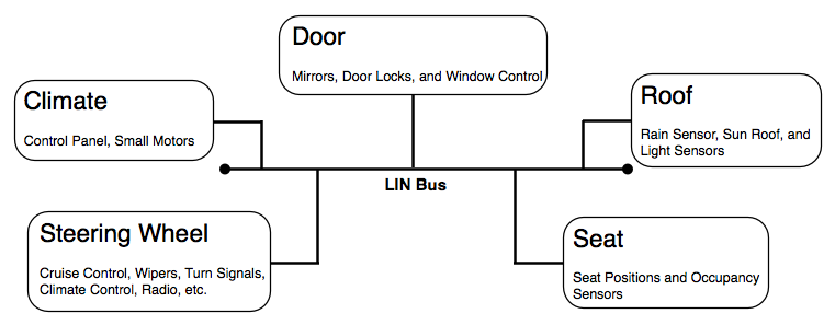
The LIN bus finds wide use in mechatronic nodes in distributed automotive applications (Figure 1). It’s designed to support hierarchical networks in industrial settings and automobiles. The current version features expanded configuration capabilities and provisions for improved diagnostic functions and interfaces.

LIN is a Commander-Responder (formerly, Master-Slave) architecture. LIN messages are initiated by the Commander, with at most one Responder replying to a message.
In some designs, the Commander acts as a Responder and replies to its own messages. Since the Commander controls all communications, LIN requires no collision detection. LIN messages are sent and received using a universal asynchronous receiver-transmitter (UART) interface. LIN nodes are typically based on microcontrollers but can be implemented with custom ICs to save power, cost, or space.
A summary of LIN network features includes:
- Single Commander with up to 16 Responders
- The Commander-Responder architecture means there’s no bus arbitration, and it’s possible to realize time-deterministic operation and guaranteed latencies
- Responder Node Position Detection (RNPD) allows node address assignment after power-up
- Single-wire communications up to 19.2 kbit/s with a 40-meter bus length. In the LIN 2.2, the speed has increased slightly to 20 kbit/s
- Variable length of the data frame (2, 4, and 8 byte).
- Configuration flexibility.
- No crystals or ceramic resonators needed to implement multi-cast reception with time synchronization
- Data checksum and error detection
- Defective node identification.
- Supports hierarchical networks
- 12 Vdc operation
LIN is standardized internationally by the ISO 17987 series, covering the requirements of the seven open systems interconnection (OSI) layers and the corresponding conformance test plans.
There’ss also a DC powerline transmission standard:
- ISO 17987-1:2016: Road vehicles – LIN – Part 1: General information and use case definition
- ISO 17987-2:2016: Road vehicles – LIN – Part 2: Transport protocol and network layer services
- ISO 17987-3:2016: Road vehicles – LIN – Part 3: Protocol specification
- ISO 17987-4:2016: Road vehicles – LIN – Part 4: Electrical physical layer specification 12 V/24 V
- ISO TR 17987-5:2016: Road vehicles – LIN – Part 5: Application program interface
- ISO 17987-6:2016: Road vehicles – LIN – Part 6: Protocol conformance test specification
- ISO 17987-7:2016: Road vehicles – LIN – Part 7: EPL conformance test specification
- ISO 17987-8:2019: Road vehicles – LIN – Part 8: Electrical physical layer specification: LIN over DC powerline (DC-LIN)
As with other ISO standards, the ISO standards for LIN have been revised to harmonize with the new inclusive language rules (‘commander’ instead of ‘master’, and ‘responder’ in place of ‘slave’). Additionally, more substantive changes are being considered.
In addition to the ISO standards, SAE provides a series of recommended practices for LIN implementations:
- SAE J2602/1: LIN Network for Vehicle Applications
- SAE J2602/2: LIN Network for Vehicle Applications Conformance Test
- SAE J2602/3: File Structures for a Node Capability File (NCF)
LIN protocol
Transmission and reception of LIN data frames are controlled by the LIN Commander using one or more pre-programmed scheduling tables. These scheduling tables contain at least the relative timing when the LIN frame sending is initiated.
A LIN frame has two parts: the header and the response. The Commander always sends the header. The response is sent by a specific LIN Responder or the LIN Commander.
LIN bit rates range from 1 to 20 kbit/s. Bit values on the bus are recessive (logical high) or dominant (logical low), and the smallest entity is one-bit time (52 µs at a bit rate of 19.2 kbit/s). The LIN bus can be in sleep or active mode. All the nodes must be in active mode when data is on the bus.
The nodes return to sleep mode after a specified quiet time and return to active mode after a wake-up frame is received. The wake-up frame can be sent by any node, including one of the LIN Responders activated by its internal software application or by the LIN Commander. After all nodes are awake, the LIN Commander schedules the next LIN frame.
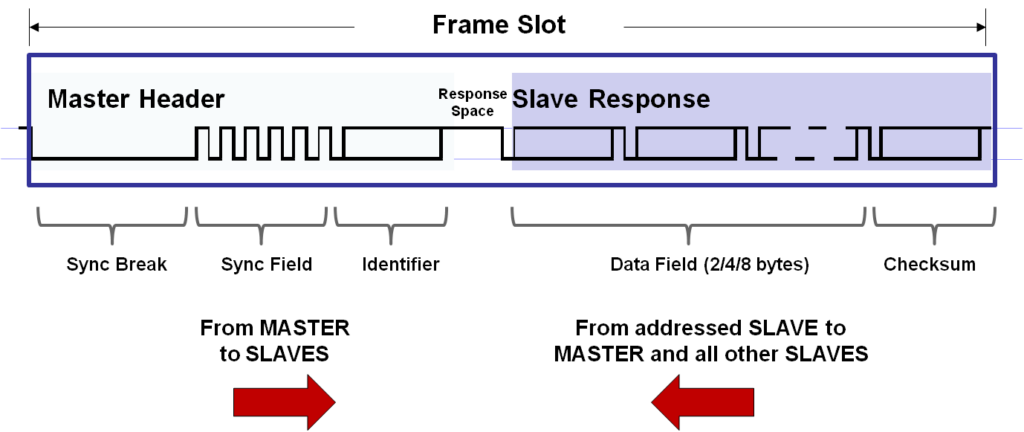
LIN data is sent in a Frame Slot which contains a Header, a Response and some Response Space so the Responder will have time to answer (Figure 2).
The LIN description file (LDF) determines the frame slot configuration. Messages begin when the Commander broadcasts a frame containing a header. One or more Responders fills the frame with the data corresponding to the header sent by the Commander. The data exchanges in the frames are called, ‘signals.’ The header includes a 1-byte Break, an Inter-Byte Space, a 1-byte SYNC, an Identifier, and a Response Space.
The Responses consist of the data and a cyclic redundancy check (CRC) byte. Responses in a LIN frame are transmitted serially as 8-bit data with one additional start bit, one additional stop-bit, and no parity bit.

Responder (Slave) will have time to answer. (Image: Microchip)
LIN verification IP
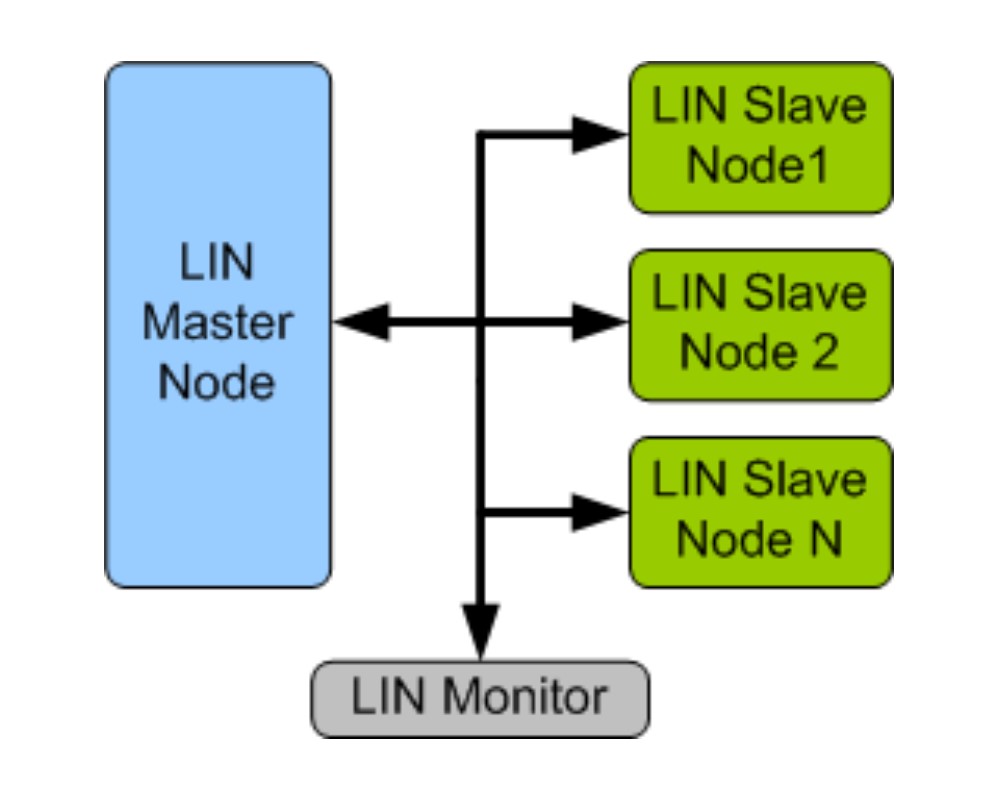
LIN verification IP are reusable components that support all LIN frame types, including Unconditional, Event-triggered, Sporadic, Diagnostic and Reserved, and provide a ready-made verification environment. These IP components comprise an extensive test suite covering most LIN usage scenarios. LIN verification tools can perform all protocol tests and generate many patterns and a set of specified patterns to stress the device under test (DUT) (Figure 3).

LIN verification IP is supported natively in SystemVerilog, verification methodology manual (VMM), reference verification methodology (RVM), advanced verification methodology (AVM), open verification methodology (OVM), universal verification methodology (UVM), Verilog, SystemC, VERA, Specman E and non-standard verification environments.
Summary
The LIN bus is a single-wire bus that enables the inexpensive integration of sensors and actuators in automobile networks. It’s optimized for mechatronic actuator systems and governed by a series of ISO and SAE standards. It’s often used to create small subnets and can communicate with a DC-LIN transceiver over a power distribution system.
LIN is limited to data rates no greater than about 20 kb/s, with a maximum of 16 nodes. These networks are based on a Commander-Responder architecture. LIN networks connect across the automobile with a backbone network such as the CAN bus.
References
- LIN (Local Interconnect Network), Clemson University Vehicular Electronics Laboratory
- LIN Message Frame, Microchip
- LIN standards and specifications, LIN Consortium
- LIN Verification IP, SmartDV Technologies
- Local Interconnect Network, Wikipedia


