Negative feedback can create a control system where the output of a process is used to counteract any deviations from a desired set point, effectively “correcting” the system, bringing it back to equilibrium, and maintaining stable operation. It’s used in a variety of applications, including voltage regulation, temperature controllers, audio amplifiers, and operational amplifiers.
This article provides a high-level overview of the maths involved in implementing negative feedback in simple voltage regulators and more complex proportional-integral-derivative (PID) industrial controllers, including how stability can be analyzed using Bode plots and the Nyquist criterion.
In a negative feedback loop, the feedback signal is out of phase with the input signal, effectively counteracting any changes that the input signal would otherwise make. That contrasts with a positive feedback loop, where the feedback signal is in phase with the input signal and reinforces changes.
Basic negative feedback for simple control systems and amplifiers involves a feedback loop where a portion of the output signal is subtracted from the input. The feedback loop gain (A) is defined as A = A₀/(1 + βA₀), where A₀ is the open-loop gain without any feedback and β is the feedback factor that represents the amount of the output signal sent back to the input.
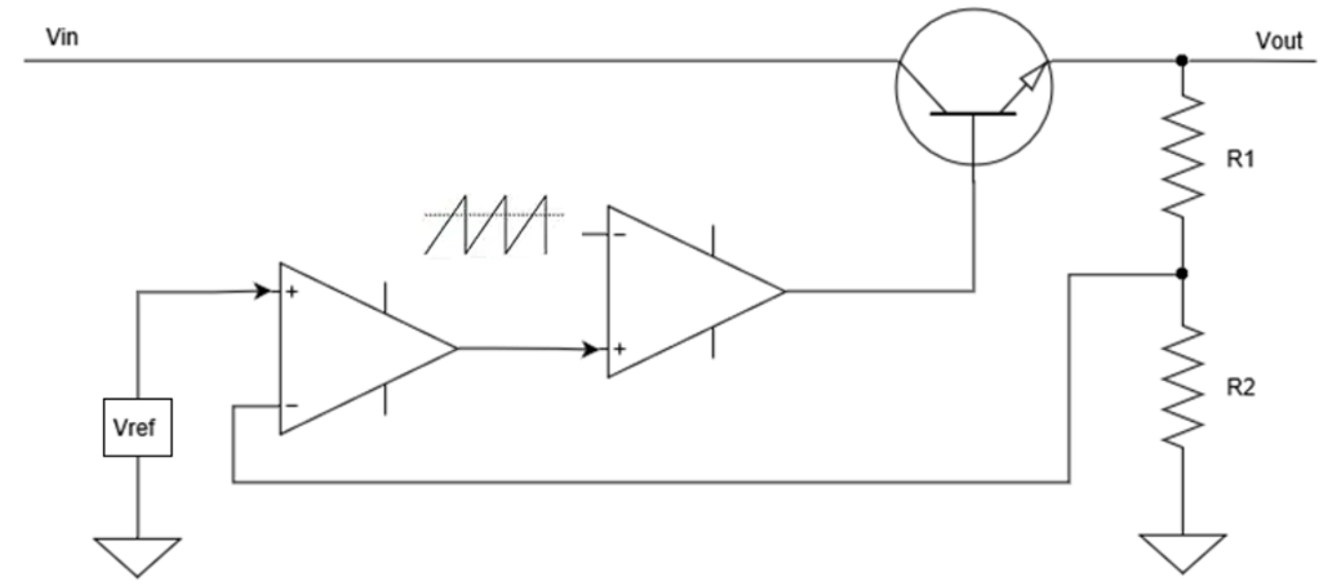
In the case of a switch-mode voltage regulator, the feedback is used to modulate the duty cycle and control the output voltage. Figure 1 illustrates the basics of switch-mode modulation. The feedback signal is compared with a reference voltage in an error amplifier. Next, the error amplifier output is compared with a ramp voltage to control the switching time.
PID controllers can provide robust and stable operation in dynamic systems. They also employ negative feedback, but the feedback computation is more complex and includes three terms, all of which are based on an error signal.
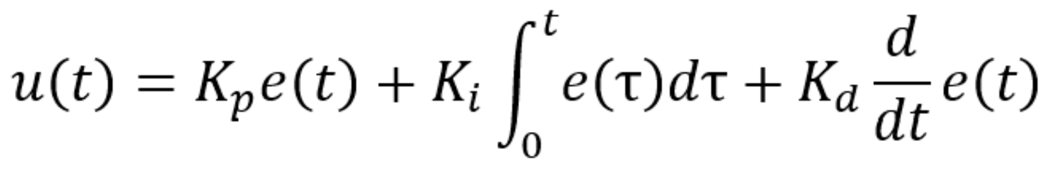
- The proportional term simply multiplies the current error by a constant, Kp.
- The integral term multiples the cumulative error by a constant, Ki.
- The derivative term multiplies the rate of change in the error by a constant, Kd.
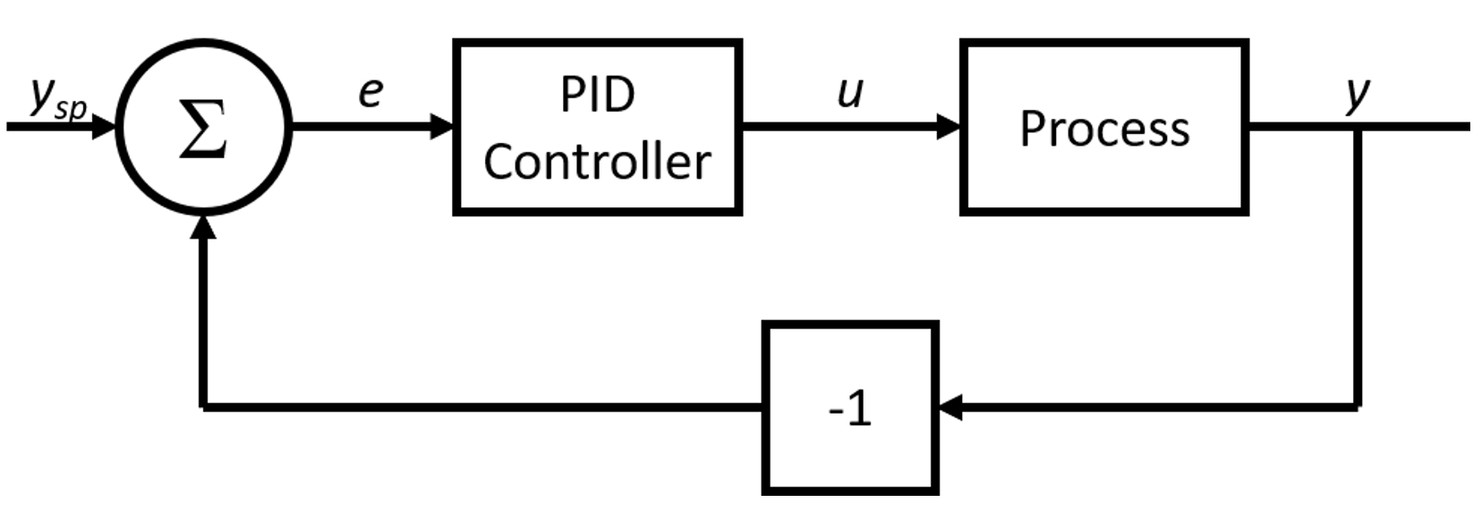
The output of the feedback loop, u(t), also known as e, or the total error factor, is fed into the PID controller to produce the control signal u for the current cycle (Figure 2).
In complex or high-performance control applications, phase shifts within the loop can result in unstable operation.
Bode plots and stability
Body plots and the Nyquist stability criteria apply to simple negative feedback systems like voltage regulators with a single control parameter and complex industrial PID controllers with multiple control parameters.

In Bode plots, the gain and phase of the feedback loop are plotted on the vertical axis against frequency on the horizontal axis. Designers use Bode plots to determine the gain margin, which indicates the amount of gain required to reach instability, and the phase margin, which indicates the amount of phase shift required to reach instability (Figure 3).
When the phase shift approaches -180°, the loop has a positive gain, ≥ 1, and can become unstable. Bode plots provide designers with a simple way to see how close the system is to that undesirable condition. Additionally, by applying a sudden load change to the regulator and observing the output voltage response, designers can assess loop stability under dynamic conditions.
Nyquist
The Nyquist criterion is another tool for stability analysis. Unlike Bode plots that display magnitude and phase separately against frequency, Nyquist plots combine them into a single complex plane representation.
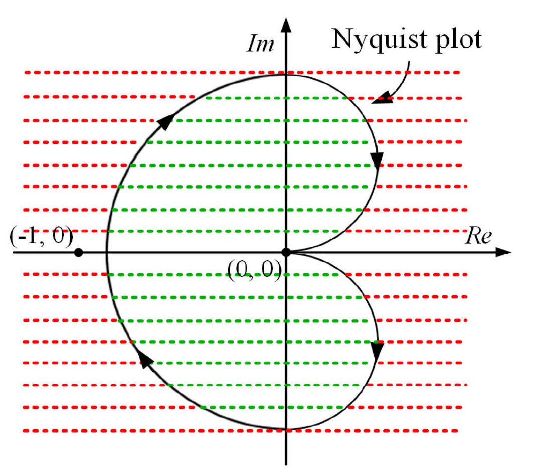
It’s a graphical technique for analyzing the frequency response of an open-loop transfer function, utilizing the Laplace transform to convert integrals and derivatives in the time domain into simple multiplication and division in the s-domain (Figure 4).
Summary
This article provides an introduction to the mathematics of negative feedback, as applied in various systems, including voltage regulators, temperature controllers, and complex industrial processes. It has also considered how Bode plots and the Nyquist criteria can be used to analyze the stability of feedback and control systems.
References
A Robust Controller Design Methodology Addressing Challenges Under System Uncertainty, IEEE Open Journal of Power Electronics
Conditional Stability in Feedback Systems, Texas Instruments
Control Loop Analysis, Tektronix
How Voltage Regulators Work, DERF Electronics
Electronic Circuit Stability: A Comprehensive Guide to Feedback Systems, Quarktwin Technology
How Does a Power Regulator Feedback Loop Work?, Cadence
PID Control Theory, Crystal Instruments
Understanding Bode plots, Rohde and Schwarz
Understanding Power Supply Loop Stability and Compensation – Part 2: Unusual or Problematic Bode Plots, Analog Devices
Why is feedback used in op-amps?, Toshiba
EE World related content
Power sequencing — options and tradeoffs: part 1
How to overcome the test and measurement challenges with WBG devices
What are the current sensing challenges with WBG power converters?
What are bidirectional GaN power ICs good for?
How can power converters be designed to minimize EMI?


Leave a Reply